Website powered by

Not forgotten...

Making Of / 26 March 2019

I know there have been big gaps in updates to the scanner 2.0 build but things are still moving forward... just very slowly...

Last week I was able to print of mounts for the upper section and on the weekend I was able to do a rough assembly.


The issue was a small measurement error in the 3D model caused a large misalignment in the physical one... :(

But I found the error so just need to make some adjustments and reprint a few parts. In the process of trouble shooting the issue I was able to rethink some design choices and managed to come up with some better solutions. 

Stay tunes as I think I'll be wrapping this up very soon, and then we can see who wants one :)  

Scanner 2.0 Phase 1

Making Of / 06 November 2018

Finally I have some real progress to share on the scanner 2.0 build. Now that I had all the pieces designed it was just finding the time to print out all the remaining parts and assemble them. Here are the parts the will makeup the octagon base of the scanner. All the light parts were supposed to be orange but I ran out so 1/2 ended up being silver.


1st step is wiring the lights. This time instead of connecting the wires directly to the bulb I used sockets. This is a little more secure and allows for easily replacing the bulbs. The lights were printed with this in mind so the sockets just need to be inserted and bolted in place.


Here all 8 lights with their sockets installed.


Now onto the mounting plates. This consists of 2 plates that sandwich the foam core panel. I went with riveting them in place as rivets are cheaper then nut&bolts and once attached they don’t need to be removed.


Here’s the final look of the front and back of the panel.


Once the plates are attached the center foam is cut out to allow for the light to be attached. The lights are then screwed to the plates. I may change this to use magnets in the future so it's simpler to assemble and break down.


All 8 panels assembled.


Ready to build the octagon. Just need to add the corner brackets to each panel and bolt them together.


And that’s it, one light octagon assembled. Without the riveting it takes about 10 min to assemble the lights and panels.


Not sure if I’ll tackle wiring next or the upper section. Wiring should be straight forward but there are 4 more lights in the upper section so may be better to wait and do all the wiring at once. Also need to decide if I’m going to add the polarizing filters to the upper lights. 

Well that’s all for now. Sorry for the long delay between posts but designing the parts to be easily replicated and that work with the constraints of 3D printing is a bit complicated. Much harder then slapping together a one off prototype with tape and hot glue 😜

I also need to figure out what to do with the scanner once it’s done. I won’t need two of them. 😗

Thanks for reading and stay tuned. Hopefully I'll be able to work on this more that I think I'm done playing with with my 3D printer. Although I did just get Red Dead Redemption 2 so that may impact things :)

PS. For what delayed me last week, I was making props for my kids Halloween costumes. My son's took the most time as he wanted a mask from PayDay2 so I downloaded a mask someone modeled online, scanned his head so I could scale it properly and printed it out. Then needed to finish it by sanding, fiberglass, glazing putty, and paint. 


Quick scanner update

Making Of / 24 October 2018

Finally got past a big step by finishing the design of the light pods and mounting plates. Yellow is the final prototype and the orange is the 1st production batch of mounting plates :)

Just have to print up the light pots now and the base will be ready to assemble!!!


Building the walls

Making Of / 19 September 2018

Here we are at take 2 of the panel design. As I mentioned in my last post the fully 3D printed panel frame wasn't going to be practical so I went with a wood frame. This was actually my original idea for the 1st scanner but making the brackets to connect them was going to be too time consuming, this was pre 3D printer though.


So I started out with a 8x4x3/4 inch board and milled it down into strips for the frame and then cut them to length. After that the slots for the panels were cut into all the strips.

The top and bottom pieces are a bit longer then the sides as they overlap the sides. They also have their ends milled to accept the brackets that hold them all together.

Here's what a panel will look like assembled. The final outer dimensions are still 12x12 inch. 

Before assembly all the frame pieces head off to the paint shop for a coat of flat black. 

Here's the 8 panels that make up the scanner painted and assembled. Also you can see how little space it takes up when disassembled for shipping to storage.

Now onto the brackets. These went though a few designs to get the size right and get the hole for the press fit nuts just the right size. The 3 white brackets were to get to this point, then I realized I had the angle of the bracket wrong, so after fixing that I tried some different colours and the red is PETG plastic instead of PLA, but I ended up just staying with white. So these brackets get added to the R&D cutting room floor.

Fresh batch of brackets coming off the assembly line :) Each bracket takes about 1hr to print so this batch take 6-7 hrs

What the bracket looks like with the hardware installed. 

And the few panels assembled. 

They assemble and break down supper fast. There is a small gap between between the panels that may/may not be a issue in the end but is nothing strip of black tap on the inside can't fix.

Now that the walls are done next is designing a fixture that will hold the lights and mount them on the panels. 

Stay tuned and thanks for Reading.

Scanner 2.0

Making Of / 05 September 2018

It's taken quite a while but I've finally started working on Version 2 of my scanner. Something a little more polished, modular so it can be dissembled for storage or shipping, and a design that can be assembled as a kit.

I recently picked up a 3D printer to help with this and I've been spending my time leaning the in's and out's of the printing world. Figuring out what is possible, best practices and doing test prints of super important stuff like Bender here. :)


Now that I have a good grasp of printing, the first task is to start at the beginning and figure out the eight side panels everything else is built on. To make this modular and a kit these panels need to easily attach together and break down for storage, but be a solid base. I'm also trying to keep the scanner the same size so each panel is a 12in x 12in square.


So my first thoughts were to stay with foam core for the panels as it's light, cheap, and ridged enough. So I would need to replace the solid wood frame with something else. I came up with a dovetail rail that on one side had a slot for the foam core panel and on the other a dovetail joint allowing the panels to slide together locking them in place. This involved a bunch of iterations to have a shape that could be printed well and test prints to get the tolerances just right so the joints weren't too tight or too loose. Also trying different print settings to speed and quality.


The final prints were done at 0.4mm resolution. Even though this was pretty coarse it cut the print time in 1/2 and as long as the dovetail pieces were printed vertically  the resolution was still high enough to have a good joint. If printed on their side the parts of the piece that were angled suffered from pretty bad stair stepping.

  Once I had a design that worked I printed out a small scale test and it came out pretty good.


There is one issue though, the time to print the full scale pieces would just take too long.

This scale test of eight pieces took 2hrs, and the full scan for all eight panels would take something like 5 days... just not particle. If I was injection molding the parts on a assembly line it wouldn't be a issue but I'm not so its back to the drawing board. I'm thinking of moving to 1/4 wood panels with wood frames so the panels are structurally sound and just need to be held together. Cutting wood strips on the table saw is a much faster process :) 

Stay tunes for more updates and if you got this far thanks for reading.

Testing the Replicator

Making Of / 06 August 2018

After getting the initial tests and calibration prints out of the way it was time to try replicating something by scanning it and the printing. 

The subject was a small clay piggy bank. Pictures below show the steps which were:

  1. Shoot images on my turn table, about 100 images or so.
  2. Construct mesh in RC. 
  3. Clean up mesh in Zbrush, then in MeshMixer create the hollow volume inside the mesh, then back to Zbrush to Boolean out the coin hole
  4. generate the .gcode file for printing in Simplify3D
  5. Fire up the printer and wait.
  6. Last is side by side comparison.

Quite happy how this all went and only took about 5-6 hrs. 1-2 hrs shooting and processing, 1-2 hrs cleaning and prepping (mostly because I was learning Meshmixer and Booleans in Zbrush), and 2 hrs printing.


Allegorithmic Blog

Making Of / 09 July 2018

I recent realized that back when I had a article posted on Allegorithmic's blog about the scanner I built and my process using the Photometric Stereo scanning nodes added to Substance designer, I never linked to in in my blog.

So I'll just leave this here :)

Scanner Upgrades

Making Of / 04 July 2018

Going forward with adding the ability to used cross polarized light meant adding some lights and in the process I made some other adjustments.

Since I was adding lights to the roof of the scanner facing down I had to loose the shroud around the lens that was blocking flare from the lights. To solve the flare issue I added shades on each light which also blocks me from being blinded when looking into the scanner, should have thought of this the first time.


Next was the lights in the top of the scanner. I added 4 lights by square columns and cutting them into the angled roof panels.

Since 1 of the lights would end up on the front panel having it removable wasn’t really going to work anymore so now it is hinges on one side and flips up and out of the way.


The top lights are wired together to 1 switch so now there will be 9 switches in total.

Next steps are to add the polarizing panels. Below is a earlier idea that I’ll probably go with. Each light will have a panel that will pivot in/out of place and be held in place with magnets.


That’s it for now, should have some more test scans soon. The extra benefit of the top lights is it will fix the falloff issue I was getting when trying to scan large areas. 

Thanks for reading.


Capturing Roughness

Making Of / 18 June 2018

I haven't posted for a while as I've been working on a few different projects, one war cross polarization.

I've been kicking around the idea of using cross polarization in my scanner since I built it to try and capture the roughness of the surface material, and I finally got around to trying some ideas. 

I tested with 2 objects, a leaf from one of my plants in the house and a piece of red vinyl which was one of the original surfaces I scan when I started doing surface scanning.

Here's what the final leaf and and vinyl materials look like rendered in Marmoset.

Keep reading past the pretty pictures to see how it was done.


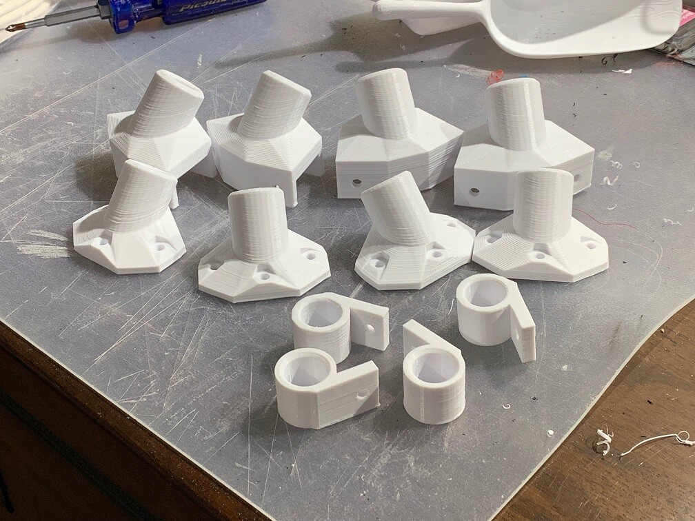
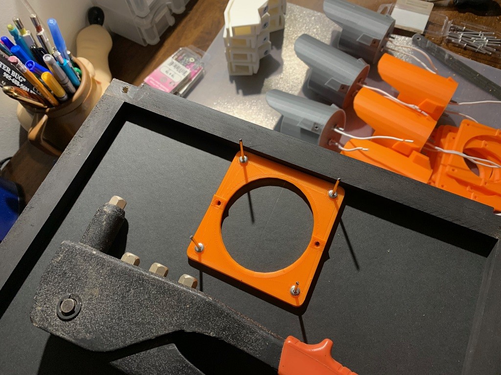
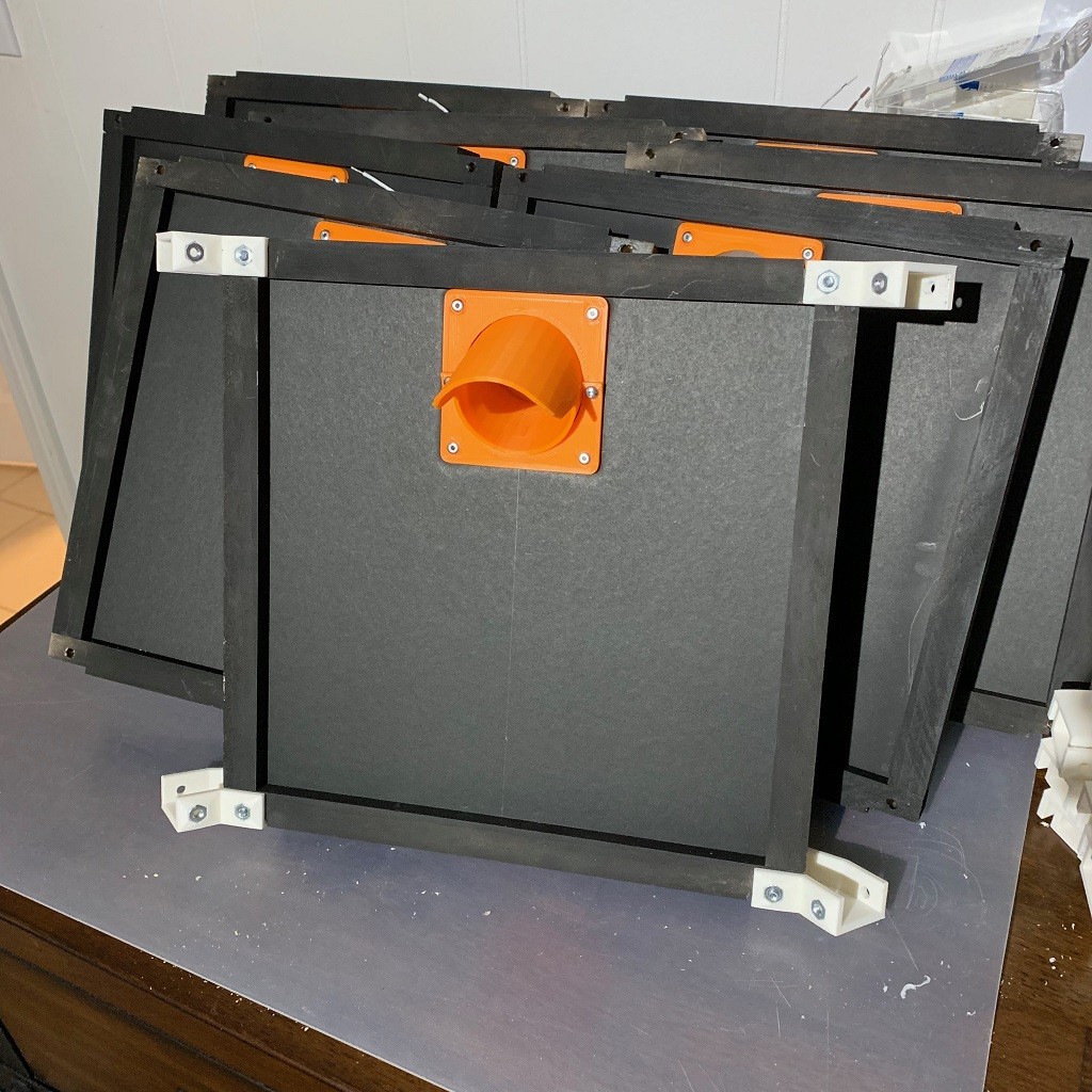
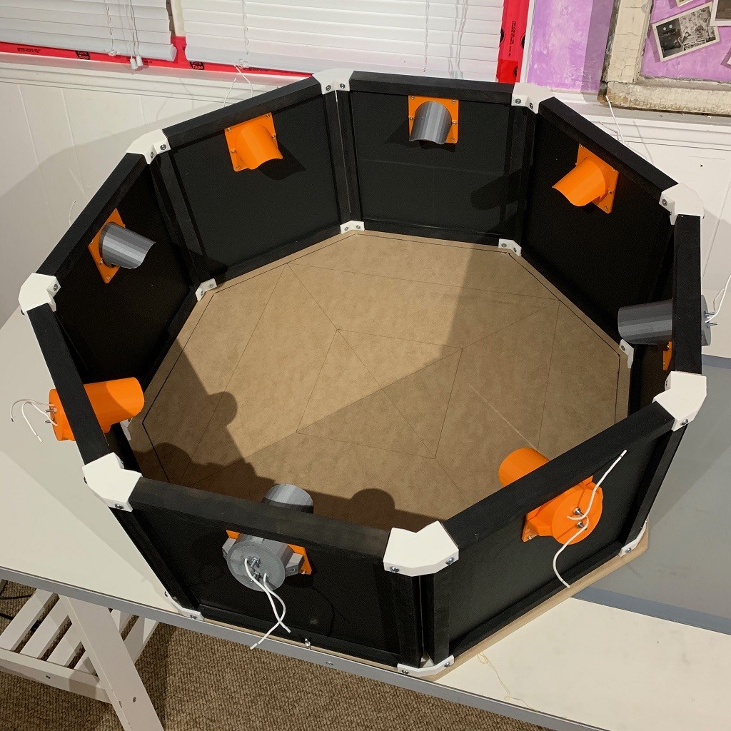
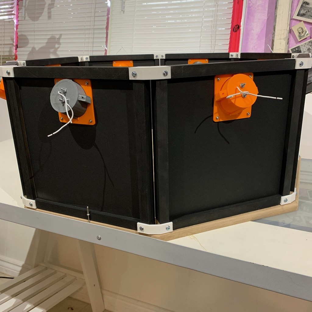
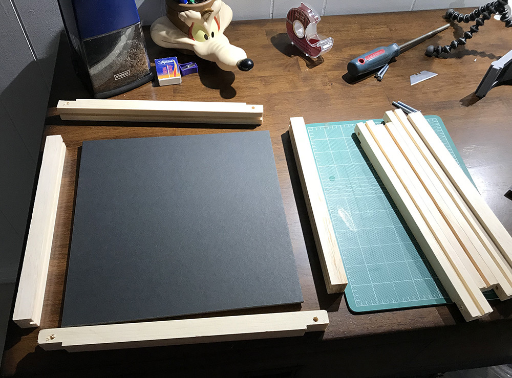
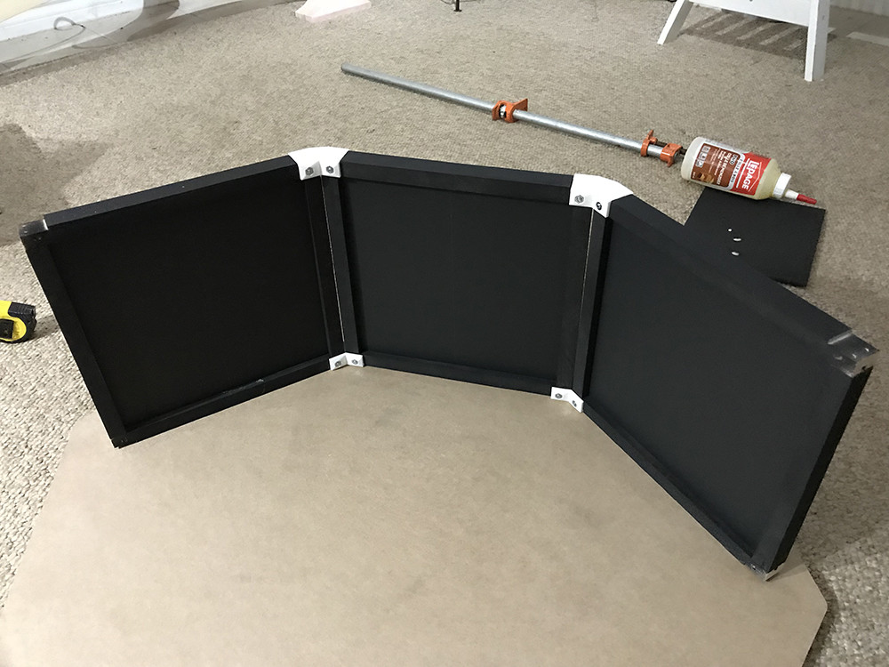
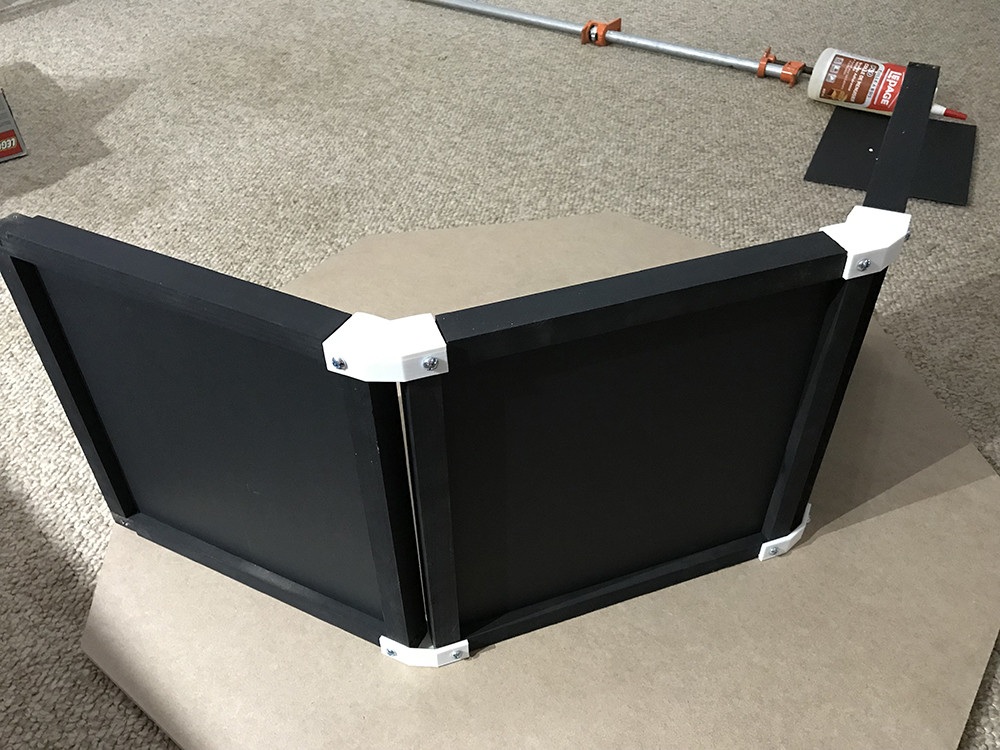
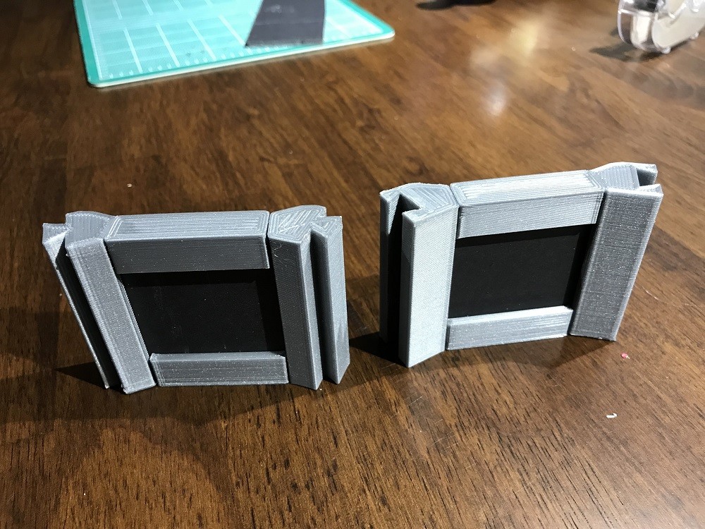
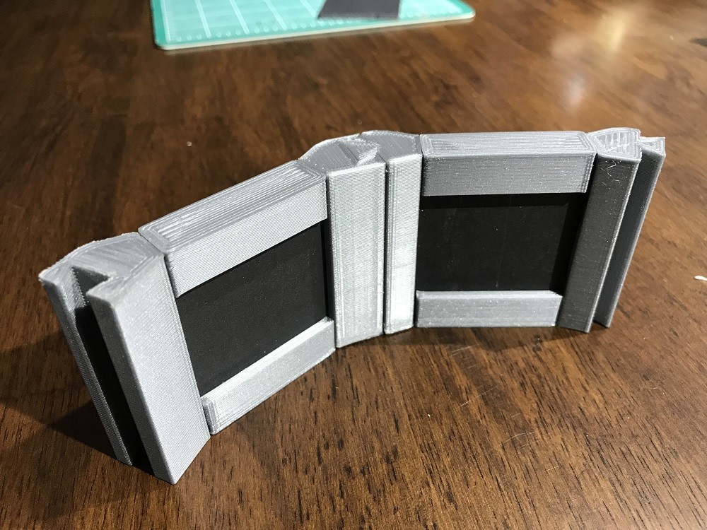
So to start I needed to add some lights to the scanner because I needed the lights facing straight onto the capture surface.For the initial testing to see if it will work I didn't want to make any drastic changes in case it didn't end up working, so I figured I could hang the lights off the internal baffle I added to keep the glare of the side lights out of the camera lens.


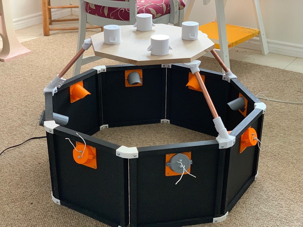
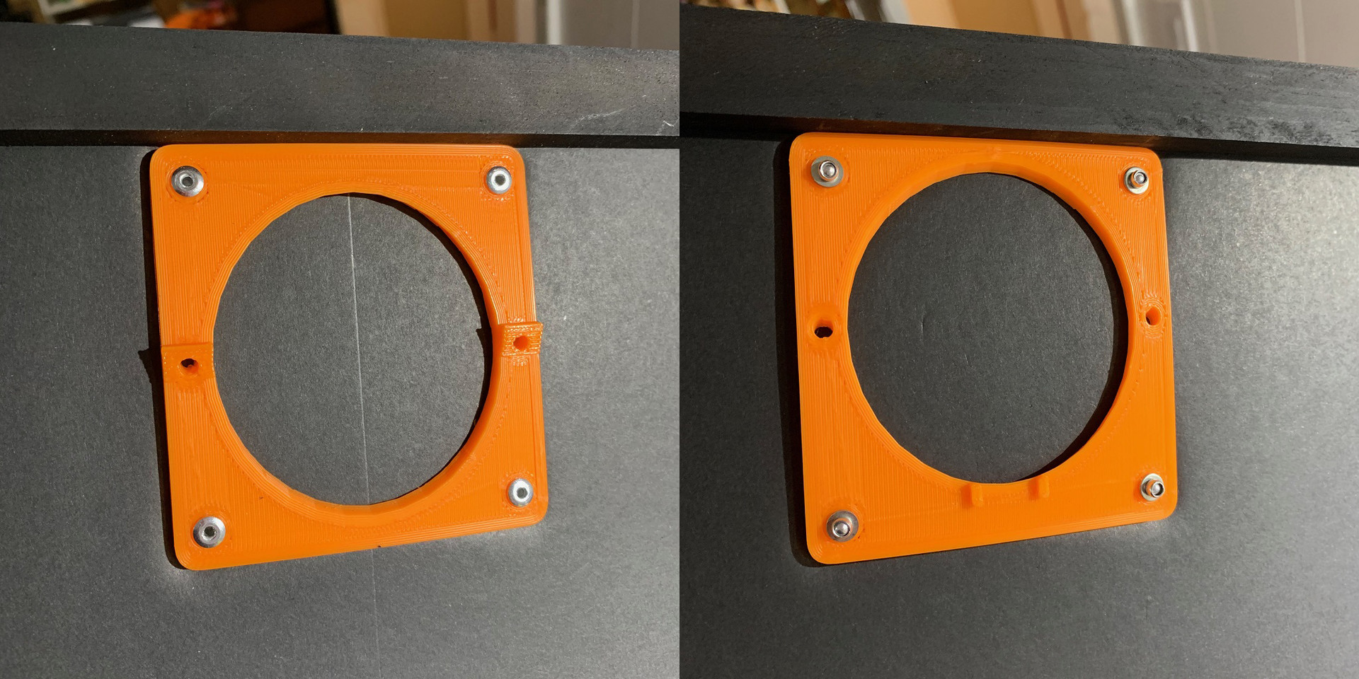
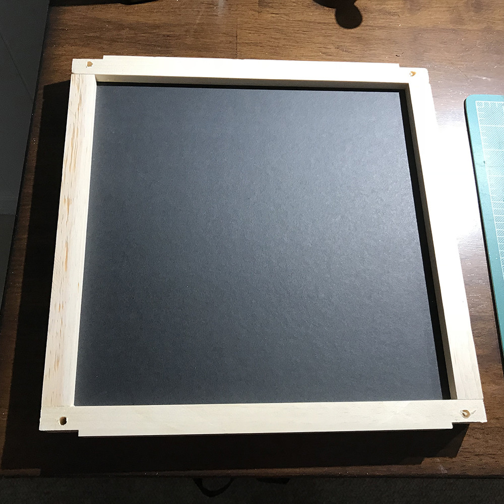
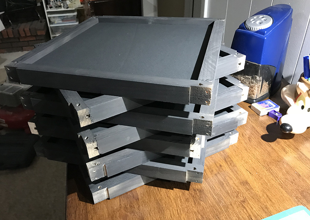
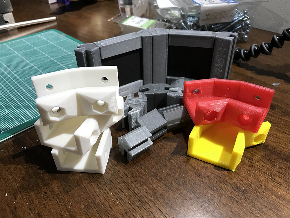
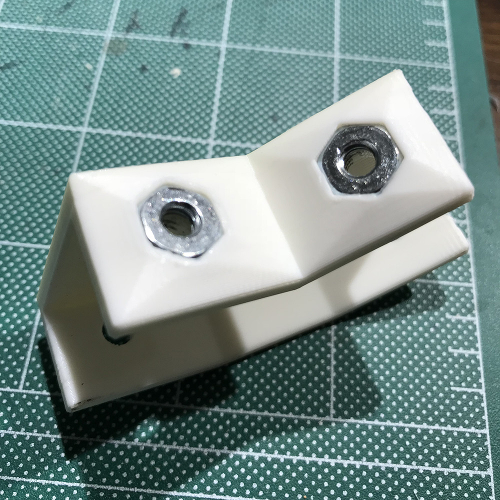
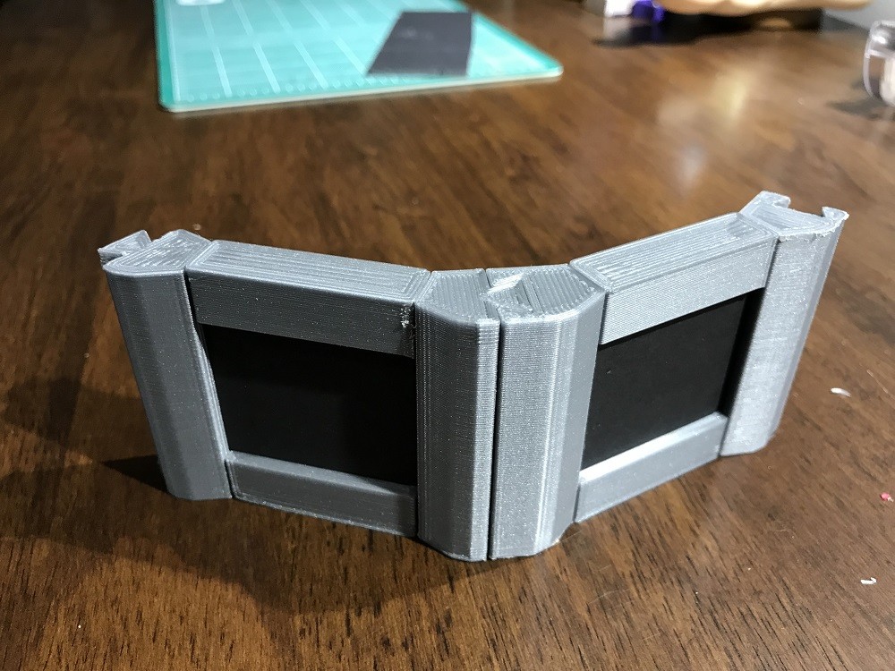
So with this idea in mind I cut out a octagon that would fit right inside the baffle to hold the lights. I went with 4 lights to try and evenly spread the light across the surface.

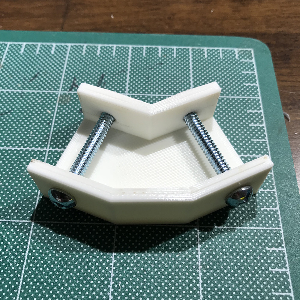
The trick was finding the right spacing and height that wouldn't interfere with the camera or cast any shadows. 

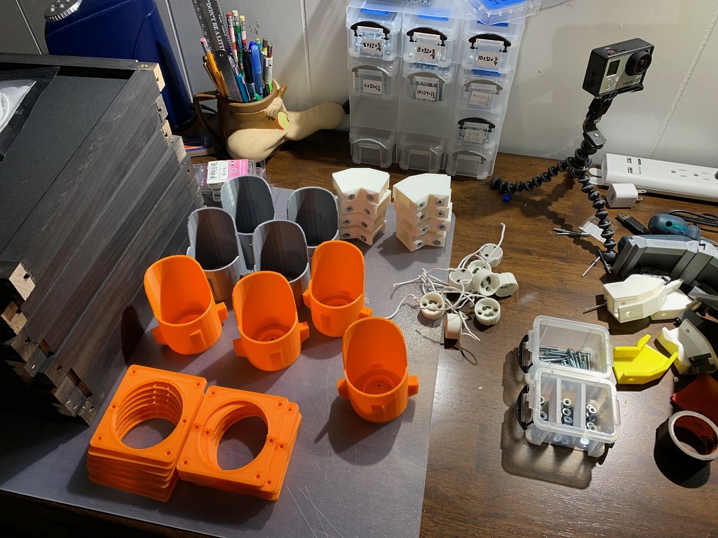
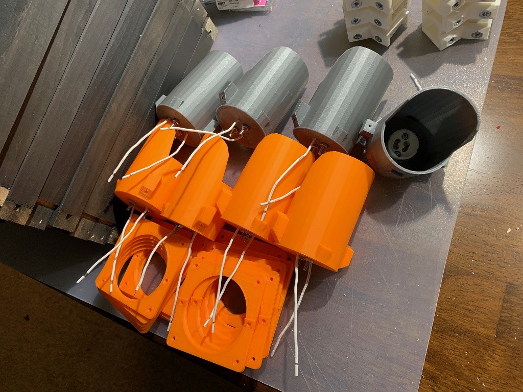
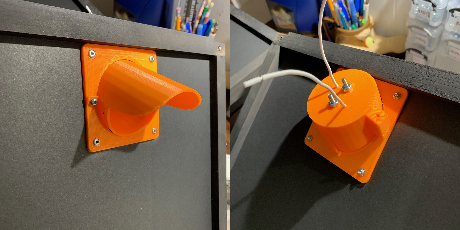
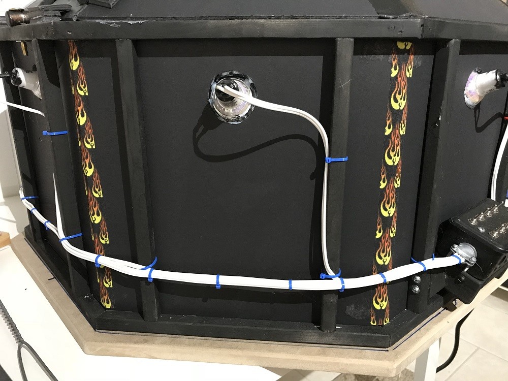
Once I had the lights glue down I wired them up. For now I just left the end wire long and stuck the wire ends into a extension cord to power them.


My 1st tests running the light were a little discouraging as there was a lot of fall off from the center of the area. I left it for a few days not thinking it was going to work, then I thought about popping the lenses off the lights just like the side lights to see if that helped, and it turned out it did. The lenses were focusing the beams too narrowly even though they were flood lights. With the lenses removed the lighting falloff was much more even.


Then there was the polarizing film. I needed to have a way to add and remove the film so I cut out a insert out of poster board with cutout for the lights and taped the polarizing film over the lights. This way I could easily add/remove the filters from all the lights at once.

Then in was just a matter of screwing on the circular polarize to the camera lens and taping the assembly onto the internal baffles and plugging them in.


And here's the results, on the left is the polarized image of the leave and vinyl and on the right is the image with the polarizesers (lens and lights) removed. The vinyl worked a little better because it could lay flat as the leaf had a few bumps in it.


Once I had the 2 images the rest was the same as usual, shooting the 8 other images with no filters to generate the normal map. Here are the 2 designer graphs. 

To generate the roughness Grzegorz Baran (go check out his ground scans) has suggested to me using a blend node to merge the two images resulting in the roughness map. So you can see that's what I'm doing on the top of the graphs, then converting the map to grey scale, inverting and then adding a level note to adjust to taste.

I'm doing the same for the leaf, except I added a mask to remove the background around the leaf. The mask was a bit off resulting in the black line on one side.


Here's what the roughness masks look like closeup. As I said above the leaf wasn't sitting flat which is causing the hot spots in the image.

I find the vinyl the most impressive when looking at the polarized diffuse image which is basically just a red square and what the final render looks like. 

Now that is seems like the process will work I'm going to look into mounting the lights differently and wiring them into the control panel.

Stay tuned for more to come and comment below if anyone has surfaces they would like to see me scan.

Thanks for reading.